INKNXMID001I000 – KNX TP-1 interface for Midea VRF systems, 1 indoor unit
INKNXMID001I000 is KNX TP-1 interface for Midea Commercial & VRF air-conditioning systems, single indoor unit, ETS configuration.


- Stock: 5-7 days
- Brand: Intesis
- Model: INKNXMID001I000
Full design package: User manual, CE declaration, CAD, PDF, certificates and test reports
If you're preparing technical documentation or an installation design, you can receive a complete set of design materials for this model. This is a quick way to gather the required documents for audits, acceptance, or project documentation.
- Device User Manual
- CE Declaration of Conformity (EU Declaration of Conformity)
- Mechanical Drawings – CAD (STEP/DWG) or high-quality PDF
- Additional Certificates and Test Reports (if available for the model)
KNX TP-1 (EIB) interface for Midea Commercial & VRF air-conditioning systems, single indoor unit, powered from the KNX bus (29 V DC), ETS configuration.
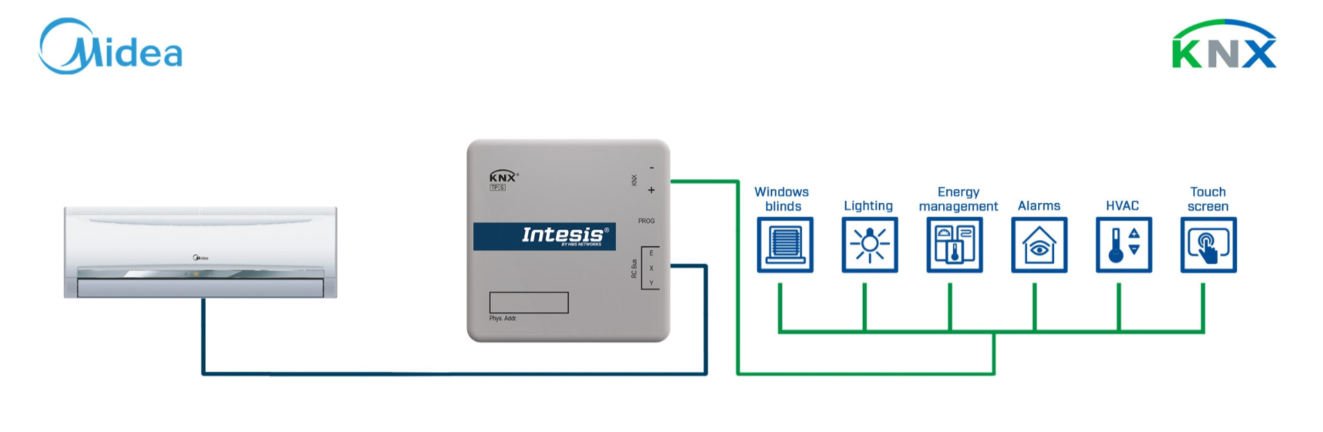
The INKNXMID001I000 interface enables seamless bidirectional communication between KNX TP-1 networks and Midea Commercial & VRF systems. It allows complete control and monitoring of the indoor unit from any KNX controller or visualization system, providing access to key HVAC functions such as On/Off, operating mode, fan speed, temperature setpoint, vane position, remote-controller lock and alarm reporting. Configuration and commissioning are handled through ETS (Engineering Tool Software), ensuring full interoperability and compliance with KNX standards.
INKNXMID001I000 – what “single indoor unit per gateway” means in real KNX projects
This interface is built for a 1:1 topology: one INKNXMID001I000 controls and supervises one Midea indoor unit over the XYE line, and exposes its HVAC functions as KNX communication objects. For multi-zone VRF/Commercial deployments, you scale by adding multiple gateways inside the same ETS project, which keeps point mapping clean, avoids cross-zone state confusion, and simplifies commissioning and service because each object set clearly belongs to one indoor unit.
Communication with the air-conditioning unit is achieved via the XYE communication port on the indoor unit, while KNX connectivity uses the standard TP-1 red/grey connector. The interface is bus-powered directly from KNX (29 V DC, 7 mA), eliminating the need for an external power supply and simplifying wiring. All HVAC operating variables are represented as standard KNX communication objects using DPT_Switch, DPT_HVACMode, DPT_Value_Temp and DPT_String. This ensures smooth integration with KNX thermostats and supervisory systems while maintaining synchronization with the local wired or IR remote controller. Parallel control via both KNX and the original Midea controller is fully supported.
Fast commissioning without guesswork – wiring + ETS + functional verification
A reliable startup sequence is typically: (1) connect KNX TP-1 (red/grey) and the 3-wire XYE to the indoor unit, (2) import the application into ETS, assign a physical address and download parameters, (3) bind the key objects to group addresses and test core commands (On/Off, Mode, Fan Speed, Setpoint), and (4) enable feedback/alarm objects to verify real status updates and diagnostics. This approach quickly separates wiring issues on XYE from ETS addressing or BMS/visualization logic problems.
KNX DPT consistency – the clean way to avoid wrong values and “missing” status
When integrating HVAC points into KNX visualizations and thermostats, the most important rule is to keep DPTs consistent end-to-end: DPT_Switch for On/Off, DPT_HVACMode for operating modes, DPT_Value_Temp for temperature values and setpoints, and DPT_String for error text. Common issues come from mismatched DPTs (temperature interpreted with the wrong format), missing feedback objects (control works but status does not update), or parallel control without a defined priority concept (local controller vs KNX logic).
The interface is supplied in a compact ABS UL 94 V-0 enclosure and can be mounted inside the indoor unit or externally using suitable protection against electrostatic discharge. Local diagnostics and programming are available via the integrated LED indicator and programming button. ETS parameters allow defining the control mode, feedback update method, pilot-lock behaviour, and default startup states. A built-in runtime counter assists in preventive-maintenance strategies. The device can manage up to 64 units per project when multiple gateways are deployed, providing flexibility for large installations.
Local diagnostics – LED + programming button as your first-line KNX check
In the field, the KNX LED and programming button are the fastest way to confirm bus presence and ETS programming state before going deeper into HVAC-side checks. If KNX is clearly alive but HVAC values do not update, the next step should be the XYE link (wiring, termination, central-controller constraints) rather than group address logic.
XYE bus best practice – termination J1 and “single central controller” rule
Pay special attention to the installation notes: if the gateway is not at the end of the XYE bus, you must disable the 120 Ω termination via jumper J1. Incorrect termination can lead to random timeouts, delayed updates, or intermittent faults that look like “software” issues. Also remember that only one central controller is allowed on the XYE line; if parallel operation with another controller is required, use the optional XYE Extension Kit to avoid collisions and unstable control.
Runtime counter and preventive maintenance – turning HVAC data into service actions
When you expose runtime counters to a KNX supervision layer, you can implement practical maintenance logic: trending, threshold notifications (e.g., filter service), and differentiating “service” events from critical alarms. This reduces downtime because service teams can act before comfort complaints appear, while critical errors can be escalated immediately.
Designed for reliable operation in professional automation environments, the INKNXMID001I000 features 4000 V galvanic isolation between KNX and AC circuits, ensuring electrical safety and EMC compliance. It operates within a temperature range of 0 … +60 °C and tolerates storage down to –40 °C. Compliance with CE (EMC & LVD) and RoHS Directives guarantees safety and environmental responsibility. Each unit includes detailed installation documentation and ETS application files downloadable from the manufacturer’s support portal.
Why 4000 V isolation matters in HVAC integration
Galvanic isolation helps protect the KNX bus from HVAC-side noise and potential differences, which is especially relevant in VRF/commercial installations where power electronics and long cable runs can introduce EMC stress. In practice, it improves robustness and reduces integration issues caused by ground loops or coupled interference.
Main features- Full KNX TP-1 ↔ Midea VRF integration (1 indoor unit per gateway).
- Direct connection to the indoor unit’s XYE port and KNX bus.
- Bus-powered (29 V DC) – no external power supply required.
- Complete HVAC object set: On/Off, Mode, Fan Speed, Setpoint, Vanes, Lock, Error Code/Text.
- Local LED and programming button for diagnostics.
- ETS configuration with standard KNX DPT types for seamless integration.
- Compact design (71 × 71 × 27 mm) for internal mounting in the indoor unit.
- 4000 V isolation between KNX and HVAC circuits, EMC compliant.
- CE and RoHS certified, 3-year warranty, manufactured in Spain.
Product features:
- 1 gateway = 1 indoor unit architecture for clean KNX point mapping in Midea VRF/Commercial projects.
- HVAC side via 3-wire XYE, automation side via standard KNX TP-1 red/grey connector.
- Bus-powered from KNX (29 V DC) – simplified installation without external PSU.
- HVAC objects exposed using KNX DPTs (DPT_Switch, DPT_HVACMode, DPT_Value_Temp, DPT_String) for thermostats and visualizations.
- Supports mixed operation: KNX control + original Midea controller in parallel.
- Local LED and programming button for quick commissioning checks.
- Alarm reporting (error code/text) and runtime counter for maintenance strategies.
- XYE installation rules supported: J1 termination and optional XYE Extension Kit for parallel controller scenarios.
Technical specifications
Identification and compliance- Model: INKNXMID001I000 (legacy ref. MD-AC-KNX-1B)
- Application: Midea Commercial & VRF systems → KNX TP-1 integration
- Configuration: via ETS software (application file available online)
- Warranty: 3 years
- Certifications: CE (EMC 2004/108/EC, LVD 2006/95/EC), EN 61000-6-2, EN 61000-6-3, EN 60950-1, EN 50491-3, RoHS
- ETIM: EC001604; WEEE Category: IT & Telecom Equipment
- ECCN: EAR99 HS Code: 8517620000 Origin: Spain
Ports and interfaces- KNX TP-1: standard red/grey connector with LED and program button.
- HVAC Port (AC): 3-wire XYE connection to indoor unit.
- Indicators: 1 LED for bus status and programming.
- I/O connections: KNX bus and HVAC (XYE) ports.
- Battery: not required.
Power supply- Input voltage: 29 V DC (from KNX bus).
- Current consumption: 7 mA typical (from KNX).
- Power consumption: ≤ 5.8 W (nominal, datasheet value).
Enclosure and mounting- Material: ABS UL 94 V-0; colour white (RAL 9010).
- Dimensions: 71 × 71 × 27 mm.
- Net weight: 42 g (User Manual) / 70 g (Product Sheet).
- Packed dimensions: 122 × 67 × 93 mm / weight 127 g.
- Mounting: inside indoor unit (preferred) or external with ESD protection.
Environmental conditions and insulation- Operating temperature: 0 … +60 °C; storage: −40 … +85 °C.
- Humidity: up to 95 % non-condensing.
- Electrical isolation: 4000 V between KNX and HVAC circuits.
Installation notes (XYE bus)- If the gateway is not at the end of the XYE bus, disable the 120 Ω termination (resistor jumper J1).
- Only one central controller is allowed on the XYE line; for parallel operation with another controller, use the optional XYE Extension Kit.
Practical answers for KNX/HVAC integrators: ETS setup, XYE bus, J1 termination, pilot lock, alarms and mixed control.
? Can INKNXMID001I000 control more than one indoor unit? ▾
No. It is a 1:1 gateway (one indoor unit per interface). Multi-zone projects scale by adding multiple INKNXMID001I000 devices within the same ETS project, keeping point mapping and service diagnostics straightforward.
? Which two connections are critical for a successful start-up? ▾
KNX side: the standard TP-1 red/grey bus connector. HVAC side: the 3-wire XYE connection to the indoor unit. If KNX is online but HVAC values do not update, the first check should be the XYE link and its termination rules.
? When should I disable the 120 Ω XYE termination (J1)? ▾
Disable the 120 Ω termination when the gateway is not installed at the end of the XYE bus. Wrong termination may cause intermittent timeouts, delayed feedback, or unstable HVAC communication that looks like an ETS issue.
? Why can another “central controller” on XYE cause unstable operation? ▾
Only one central controller is allowed on the XYE line, and INKNXMID001I000 operates as a central controller. If parallel operation with another controller is needed, use the optional XYE Extension Kit to avoid bus collisions and random control issues.
? Which KNX objects are essential so visualization does not “lose” HVAC status? ▾
Besides control objects (On/Off, Mode, Fan Speed, Setpoint, Vanes), enable feedback and alarm objects (Error Code/Text). Ensure the DPT types are consistent in ETS and the supervisory layer (DPT_Switch, DPT_HVACMode, DPT_Value_Temp, DPT_String) to avoid wrong values or missing updates.
? Can the indoor unit be controlled from KNX and the original Midea controller at the same time? ▾
Yes. Mixed control is supported. In practice, define a clear priority concept in the KNX logic (schedules/limits) so local user actions and KNX automation do not continuously override each other.
? What should I check if KNX is online but HVAC does not react? ▾
Check the 3-wire XYE wiring and connector seating at the indoor unit, then verify J1 termination settings. Next, rule out a second central controller on XYE without the Extension Kit. Only after that, validate ETS object mapping, feedback parameters, pilot-lock behaviour and startup defaults.
? What is the benefit of 4000 V galvanic isolation between KNX and HVAC circuits? ▾
It improves electrical safety and EMC robustness by reducing the risk of ground loops and noise coupling between HVAC electronics and the KNX bus, especially in commercial VRF installations with long cable runs and power electronics.
Warranty and certifications
- Warranty: 3 years manufacturer’s warranty.
- Certifications & standards: CE (EMC/LVD), EN 61000-6-2, EN 61000-6-3, EN 60950-1, EN 50491-3, RoHS.
- Classifications: ETIM EC001604 / WEEE IT & Telecom Category.
Example of integration