IN770AIR00MO000 – Multi-brand AC Interface for Mitsubishi Electric
IN770AIR00MO000 is Multi-brand AC Interface for Mitsubishi Electric, temp. 0…+60°C, DIN rail, cert UL/CE.

- Stock: 5-7 days
- Brand: Intesis
- Model: IN770AIR00MO000
Full design package: User manual, CE declaration, CAD, PDF, certificates and test reports
If you're preparing technical documentation or an installation design, you can receive a complete set of design materials for this model. This is a quick way to gather the required documents for audits, acceptance, or project documentation.
- Device User Manual
- CE Declaration of Conformity (EU Declaration of Conformity)
- Mechanical Drawings – CAD (STEP/DWG) or high-quality PDF
- Additional Certificates and Test Reports (if available for the model)
Multi-brand AC interface with Modbus, KNX, Serial and IP integration.
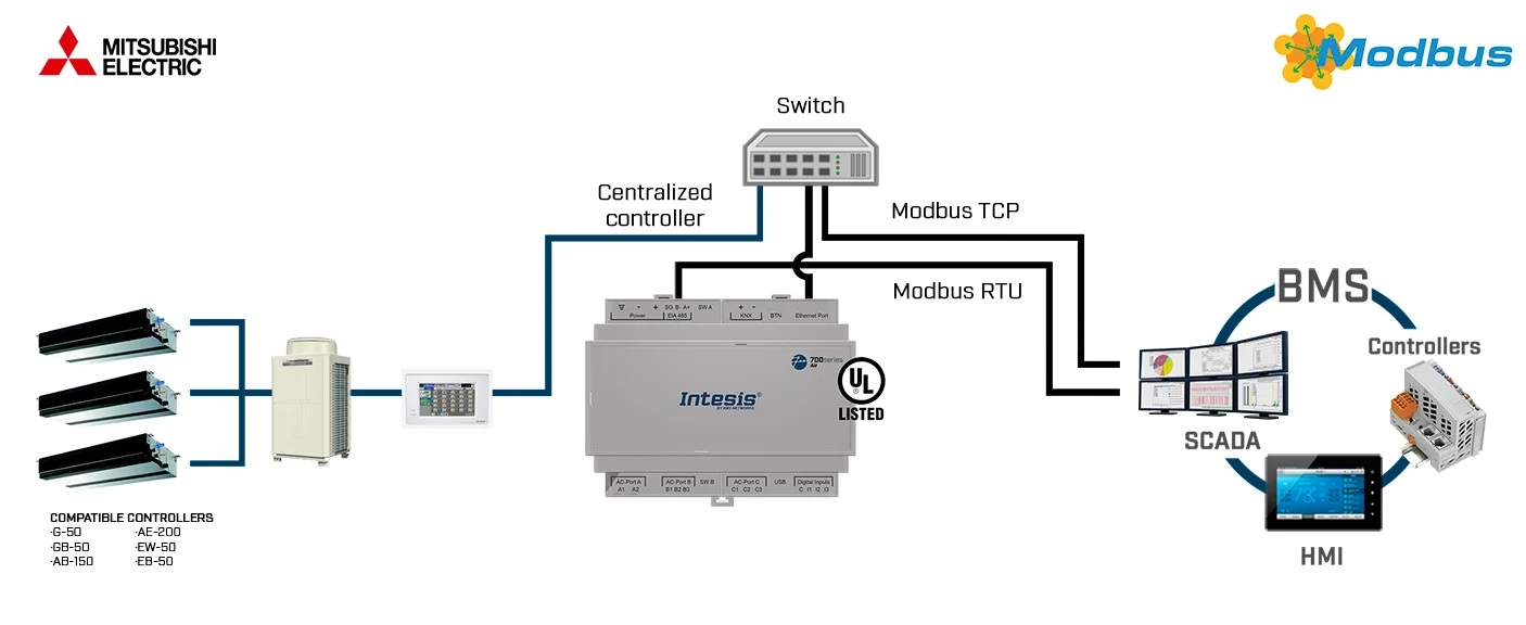
The IN770AIR00MO000 is a universal multi-brand HVAC gateway designed for integrating VRF and multi-split systems from leading manufacturers such as BOSCH, Daikin, Hisense, Hitachi, Midea, Mitsubishi Electric, Panasonic and Samsung with building automation platforms through KNX, Modbus RTU/TCP and open ASCII/IP. It offers full two-way control, monitoring and data acquisition from indoor and outdoor units, making it suitable for commercial, industrial and large-scale residential automation.
Capacity and licensing: what “00MO000” means for the project scope
The IN770AIR00MO000 corresponds to a Medium capacity license. In the IN770AIR***O000 family, the license defines the maximum number of AC units that can be discovered, mapped, and supervised by the gateway. For the Medium tier, this ceiling is up to 64 indoor units and up to 64 outdoor units, which directly impacts how you size a gateway for hotels, office floors, retail chains, and multi-zone VRF topologies. :contentReference[oaicite:0]{index=0}
A key architectural characteristic of this device is that it operates as a Central Controller on the native AC communication bus. Because most VRF buses allow only one Central Controller to be connected at a time, the gateway must be the only controller on the line. If another Central Controller must coexist in the same installation, an XYE Extension Kit is required to ensure compatibility and proper multi-controller operation.
How the gateway behaves as a “server” toward BMS/SCADA/PLC
In typical BMS architecture, the gateway acts as a server device for the automation side. It continuously polls the HVAC network, stores the latest values in memory, and serves them to KNX and Modbus clients on demand. When a mapped signal changes, the gateway can propagate the new state to the automation side, wait for a response, and apply the corresponding action to the HVAC system. If a signal does not respond, a communication error is triggered, helping you pinpoint which signal and which unit is failing. :contentReference[oaicite:1]{index=1}
The interface automatically adapts its behaviour to the connected AC brand. It supports multi-indoor and multi-outdoor topologies with brand-specific limits and dedicated terminal types. This flexibility makes the device a powerful, vendor-independent integration layer for BMS, SCADA and PLC systems.
Brand-specific capacities & bus connections
- BOSCH: up to 64 indoor units — connected via XYE terminals
- Daikin: up to 64 indoor units and 10 outdoor units — connection via F1/F2 terminals
- Hisense: up to 64 indoor units and 64 outdoor units — connection via AB (H-Link)
- Hitachi: up to 64 indoor units and 64 outdoor units — connection via AB (H-Link)
- Midea: up to 64 indoor units — connection via XYE terminals
- Mitsubishi Electric: up to 100 VRF groups — connection through Mitsubishi Electric Centralized Controller bus
- Panasonic: up to 64 indoor units and 32 outdoor units — connection via U1/U2 (P-Link)
- Samsung: up to 64 indoor units and 16 outdoor units — connection via R1/R2 terminals
The gateway supports simultaneous Modbus TCP and Modbus RTU communication, with up to 6 concurrent TCP clients. This ensures full compatibility with complex BMS and supervisory systems requiring parallel access to HVAC data. The device exposes a comprehensive data model including alarms, status variables, temperatures, setpoints and full indoor/outdoor unit operation values.
IP commissioning: DHCP window and fallback IP
For first-time commissioning (or after a factory reset), the gateway enables a temporary DHCP mode for 30 seconds when an Ethernet link is detected. If a DHCP server assigns an address during that window, you can discover and configure the device within the building LAN. If no DHCP server is available, the gateway falls back to the default IP address 192.168.100.246 after the 30 seconds elapse. This is a practical detail for on-site start-up in VLAN environments and for point-to-point laptop commissioning. :contentReference[oaicite:2]{index=2}
RS-485 engineering constraints: termination, polarization, and bus limits
If you deploy Modbus RTU on EIA-485, observe standard bus restrictions: a maximum of 1200 m total line length and up to 32 devices per segment. Terminate the line with 120 Ω at each end. The gateway includes internal termination and biasing that can be enabled using the dedicated DIP switch block for the EIA-485 port: position 1 for 120 Ω termination, and positions 2 and 3 for polarization. If you enable the gateway’s termination at the end of the bus, do not add an extra resistor at that same end. :contentReference[oaicite:3]{index=3}
System commissioning is simplified with Intesis MAPS, which provides configuration, diagnostics, real-time bus monitoring and firmware updates. The unit includes Ethernet, RS485, KNX and USB console connectivity, making it highly adaptable for both distributed and centralised automation environments.
Wiring discipline and installation hygiene (SELV, cabinet, and earth loops)
For long-term stability in industrial cabinets, mount the gateway indoors in a restricted access location, preferably on a DIN rail inside a grounded metallic enclosure, and keep communication cables away from power and ground conductors. Use SELV-rated NEC class 2 or LPS power supplies; apply 12..36 VDC (±10%) or 24 VAC (±10%) as specified. To reduce the risk of earth loops, prefer floating DC supplies (or negative tied to earth) and avoid DC supplies with positive tied to earth. Use a circuit breaker between the gateway and power supply (rating 250 V, 6 A). :contentReference[oaicite:4]{index=4}
Key features
- Support for up to 100 Mitsubishi Electric VRF groups
- Simultaneous operation with Modbus RTU and Modbus TCP
- Up to 6 TCP clients can connect at once
- Automatic scanning of indoor units on VRF system
- Energy consumption and outdoor unit data exposed
- KNX TP interface and open ASCII protocol for IP integration
- Direct Ethernet port for seamless LAN integration
- Fast setup and firmware upgrades via Intesis MAPS or USB
- LED indicators for diagnostics and communication status
- Robust DIN rail or wall mounting, IP20-rated housing
Specifications
Enclosure:
- Plastic, PC (UL 94 V-0)
- Dimensions: 90 × 106 × 58 mm
- Installation space: 130 × 115 × 100 mm
- Color: Light Grey (RAL 7035)
Mounting:
- Wall mount: M3 screws (25 mm)
- DIN rail EN60715 TH35
Terminal wiring:
- 1 core: 0.5–2.5 mm² (24–11 AWG)
- 2 cores: 0.5–1.5 mm² (24–15 AWG)
- 3 cores: not permitted
- Use class 2 cables for distances > 3.05 m
Connector map and what each port is for
The device provides a dedicated TCP/IP Ethernet interface (for IP-based communication and configuration), an EIA-485 interface for serial fieldbuses, a KNX TP connector for KNX bus integration, USB (Type-C) for local PC connection, and AC ports reserved for the native HVAC bus connection. For binary energy metering, the digital inputs are designed for dry contact metering only and must not be driven with voltage. :contentReference[oaicite:5]{index=5}
Power supply:
- Green 3-pole terminal block
- 12–36 VDC ±10 %, max. 250 mA
- 24 VAC ±10 %, max. 127 mA (recommended: 24 VDC)
Ethernet:
- 1 × Ethernet 10/100 Mbps RJ45
Port EIA-485:
- 1 × 3-pole terminal block, 1500 VDC isolation
KNX port:
- 1 × orange 2-pole plug-in block (A, B)
AC ports:
- AC Port A: Serial 2 poles
- AC Port B: Serial 3 poles
- AC Port C: Serial 2 poles
- (Not used for this integration)
LED and button behavior useful during commissioning
During start-up, the front LEDs provide immediate feedback for power, hardware errors, and bus activity (Tx/Rx) on each interface. The push button can be used for factory reset (hold during power-up, release after four seconds). Depending on the active project, the same button can toggle KNX programming mode or trigger a BACnet “I-Am” message on the BACnet side. :contentReference[oaicite:6]{index=6}
LED indicators:
- Run (Power/Error), EIA-485 Tx/Rx, KNX Tx/Rx
- Ethernet Link/Speed, AC Ports A/B/C Tx/Rx
- Button status
Binary inputs:
- 4-pole terminal block (I1, I2, I3, Common)
- 1500 VDC isolation
Console port:
- Mini USB Type-B 2.0, 1500 VDC isolated
Environmental:
- Operating temperature: 0 °C to +60 °C
- Humidity: 5–95 %, non-condensing
- Protection: IP20 (IEC60529)
Practical answers for BMS/HVAC integrators: licensing, wiring, IP commissioning, and fieldbus stability.
? What is the maximum number of AC units supported by IN770AIR00MO000? ▾
IN770AIR00MO000 is the Medium license variant and supports up to 64 indoor units and 64 outdoor units within the IN770AIR***O000 family.
? How does IN770AIR00MO000 obtain its IP address during first commissioning? ▾
When an Ethernet link is detected on first start (or after factory reset), the gateway enables DHCP for 30 seconds. If no DHCP lease is obtained, it automatically sets 192.168.100.246 as the default IP.
? Why does the “Central Controller” requirement matter for IN770AIR00MO000? ▾
Most VRF buses allow only one Central Controller. If another Central Controller is present, bus arbitration conflicts can break write operations. Use the XYE Extension Kit when parallel controllers must coexist.
? What are the key RS-485 rules for stable Modbus RTU with IN770AIR00MO000? ▾
Follow EIA-485 constraints: 1200 m max segment length, 32 devices max per bus, and 120 Ω termination at both ends. Enable the gateway’s internal termination/polarization via DIP switches when it sits at the end of the bus, and do not add a second resistor at that same end.
? How can I quickly diagnose “no response” issues in the field? ▾
The gateway polls the HVAC network continuously and raises a communication error when a mapped signal does not respond. Use Intesis MAPS diagnostics to verify bus activity (Tx/Rx), confirm unit discovery, and isolate the failing unit/signal pair before adjusting wiring or addressing.
? What is the safest way to power IN770AIR00MO000 to avoid ground loops? ▾
Use a SELV-rated Class 2 / LPS supply. Prefer floating DC supplies (or negative tied to earth), avoid DC with positive tied to earth, and use an upstream circuit breaker (250 V, 6 A). Apply 12–36 VDC or 24 VAC within the specified current limits.
? How do I factory-reset IN770AIR00MO000 during commissioning? ▾
Press and hold the push button, power on the gateway, wait 4 seconds, and then release. This restores factory settings and erases the project and configuration.
? Can I use the digital inputs to read third-party sensors with IN770AIR00MO000? ▾
No. The digital inputs are designed for potential-free (dry contact) energy metering only and must not be driven by external voltage. Use appropriate I/O modules if you need general-purpose sensing.
Warranty: 36 months
For driver downloads, integration examples or firmware support, contact our experts via this form.
")

