Modbus Gateway configuration in practice: RTU/ASCII to Modbus TCP settings for BMS

- Why does Modbus gateway configuration have a real impact on BMS stability?
- When do you need a Modbus RTU/ASCII ↔ Modbus TCP gateway?
- Start: wiring, web access, and first login
- Operating modes: RTU Master/Slave and ASCII Master/Slave – how to choose?
- Mode Settings: routing by IP/port, Smart Mode, and timeouts
- Slave ID Mapping: auto-route, manual, and offset (Visual ID ↔ Real ID)
- Priority Control: request priorities and critical registers
- Testing and diagnostics: how to quickly find the bottleneck
- FAQ
Why does Modbus gateway configuration have a real impact on BMS stability?
In BMS projects and industrial automation, Modbus is a “common language” for energy meters, HVAC controllers, regulators, and many field devices. The problem is that having the protocol alone does not guarantee stable communication: in practice, system quality is determined by configuration details – from RS-485 parameters, through ID mapping, to priorities and timeouts.
That’s why a well-chosen and correctly configured Modbus gateway (Modbus Gateway) is often the component that “ties” the system together and reduces the risk of random timeouts, request queues, and consequently alarms and incorrect readings. In this guide, we go step by step through the settings that make the biggest difference in real deployments.
If you are looking for a proven device for RTU ↔ TCP conversion, see: GW1101-1D(RS-485) – Modbus RTU/ASCII to Modbus TCP gateway.
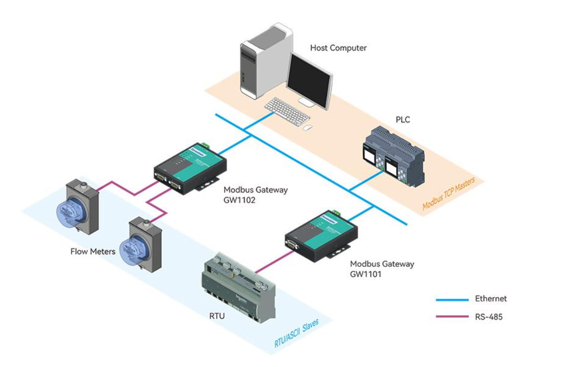
When do you need a Modbus RTU/ASCII ↔ Modbus TCP gateway?
The most common BMS scenario looks like this: the server/master controller runs on an IP network and “speaks” Modbus TCP, while field devices (energy meters, regulators, sensors) run on RS-485 with Modbus RTU. The Modbus gateway then acts as a translator: on one side it receives TCP requests, on the other it sends them over RS-485 to the correct slave and returns the response.
Another common case is integration “the other way around”: you have an existing RS-485 infrastructure and devices that expect Modbus RTU/ASCII, but you want to expose the data to an IP system (SCADA/BMS/PLC) without rewiring the entire bus.
In practice, gateways are also chosen when you need order in addressing (ID mapping), control of priorities (critical registers), or when you want to limit the number of requests to slow devices (Smart Mode and response buffering).
Start: wiring, web access, and first login
1) Physical wiring and mounting
Connect Ethernet to the network (or directly to a laptop during commissioning) and RS-485 to the Modbus RTU bus. By default, devices in this series are designed for desktop or wall mounting, but in a control cabinet it is common to use DIN rail mounting via an adapter/bracket – so the gateway fits neatly alongside typical automation components.
2) Set the PC IP and open the web panel
For initial configuration, the easiest approach is to set your computer in the same subnet as the device. By default, the gateway’s web panel is available at http://192.168.1.254, so the PC IP should be in the same segment (e.g., 192.168.1.x). On some devices you may also encounter Dual IP mode, where the second Ethernet port has its own address (often 192.168.8.254). Log in with admin/admin and pay attention to selecting Modbus Gateway in the top-right corner of the interface.
If you deploy the gateway in an existing building network, set the target IP from the start and ensure: default gateway, DNS (if required), and routing rules. You will avoid the classic “works locally, doesn’t work from the BMS server” situation.
Operating modes: RTU Master/Slave and ASCII Master/Slave – how to choose?
In the Modbus Gateway panel, you choose the operating mode for the serial port. Four variants are available: RTU Master, RTU Slave, ASCII Master, ASCII Slave. The selection is straightforward if you answer one question: who is the master on the RS-485 side?
- RTU Slave – most common in BMS: on Ethernet you have a TCP master (BMS/SCADA), and on RS-485 you have RTU slave devices.
- RTU Master – when a master exists on RS-485 (e.g., a controller/PLC) and on Ethernet you want to poll TCP slaves.
- ASCII Master / ASCII Slave – the same logic but for Modbus ASCII (less common in new BMS, sometimes in legacy systems).
It is also worth knowing that, depending on the mode, the gateway supports concurrent TCP sessions: in slave modes (RTU/ASCII Slave) it can work with many TCP masters simultaneously, and in master modes (RTU/ASCII Master) it can connect to many TCP slaves. This matters if, for example, two supervisory systems must read the same data (BMS + EMS).
Mode Settings: routing by IP/port, Smart Mode, and timeouts
Basic configuration is located in Protocol Settings → Mode Settings. Here you set the port operating mode, and (optionally) routing by IP address or TCP port – meaning which requests should be forwarded to a given serial port. This is especially useful if you have multiple RS-485 ports or want to separate traffic from a specific supervisory system.
Smart Mode (intelligent request learning)
Smart Mode can “learn” Modbus commands and buffer responses so the master can read them without continuously loading the slaves. In practice, this can be helpful with slow devices, long RS-485 lines, and systems that would otherwise poll registers too aggressively. Key settings include polling interval and data aging times.
Timeouts and delays – why is this critical on RS-485?
If an RTU device cannot respond to multiple requests at once (which is typical), the request queue can become “clogged”. That’s why well-chosen Response timeout and Inter-Frame Delay often stabilize communication: you avoid retry storms and you don’t block the bus. Additionally, in “Advanced Settings” you can find, among other things, an initial delay, which helps avoid a “cold start” where all communication kicks in at once after a power restart.
Slave ID Mapping: auto-route, manual, and offset (Visual ID ↔ Real ID)
This is the area that most often “saves” deployments. In Protocol Settings → Slave ID Mapping you configure how Modbus requests should reach the correct slave – both over TCP and on RS-485. You can choose automatic mode (Automatic Route) or manual mode.
Manual mode provides the highest level of control because it allows mapping the Visual ID seen by the master to the device’s Real ID (via offset). This is perfect when you cannot change physical addresses on the bus (because they are already documented), but you want to organize addressing “from the BMS side” without the risk of service downtime.
You want the BMS to poll devices as ID 10–20, but physically on the bus you have ID 1–11. You set the offset so that Real ID = Visual ID + offset. This way you don’t touch device addresses, while the BMS gets “clean” IDs.
The result is faster deployment and fewer mistakes in documentation.
Priority Control: request priorities and critical registers
On RS-485 many slave devices process requests sequentially. When traffic is heavy, requests can “stack up”, and this hurts most where you have critical registers (e.g., alarms, protections, control signals). That’s why it is worth using Protocol Settings → Priority Control to assign priority: by TCP port, by master address, or even by specific requests (Slave ID / Function Code / Data).
In practice, BMS implementations often do this: monitoring “hard” alarms gets priority, while “soft” readings (e.g., statistics, trends) are handled in the background. The effect is faster system response and fewer false timeouts during critical moments.
Testing and diagnostics: how to quickly find the bottleneck
The best post-configuration test is one that simulates real load: several devices, typical polling cycles, and register writes. If something “doesn’t hold”, start with fundamentals: port parameters (baud/parity/stop bits), RS-485 termination and biasing, unique slave IDs, and only then move on to priorities and mapping.
On the device itself, it is worth checking serial port error counters (Frame/Parity/Overrun/Break). If they increase, it usually means the issue is physical (wiring, interference) or transmission parameters are mismatched.
If you want, I can prepare a “mini deployment checklist” for BMS (RS-485: topology, termination, shielding; Modbus: function codes, retry/backoff; gateway: timeouts and priorities) and tailor it to your most common cases from GSC.
FAQ – Modbus gateway in BMS and automation
Does a Modbus gateway replace a BMS controller?
No – the gateway is an intermediary device for conversion and routing; control logic remains on the BMS/PLC side.
Which mode is most commonly used in BMS?
Most often RTU Slave, because BMS/SCADA acts as a Modbus TCP master and field devices are Modbus RTU slaves on RS-485.
What is Slave ID Mapping for?
To organize routing and addressing: you can map Visual ID to Real ID and avoid changing physical device addresses on site.
When is Priority Control worth using?
When you have heavy traffic and part of it is critical (alarms/control). Priorities reduce response time and limit queues.
Why can Modbus RTU “timeout” despite correct wiring?
Most often due to overly aggressive polling, poorly chosen timeouts, or a request queue hitting a slow slave – gateway tuning helps here.
Which gateway should I choose for typical RTU ↔ TCP?
In many deployments, 1× RS-485/422 + 1× Ethernet is enough, e.g., GW1101-1D(RS-485) – the rest depends on segments and port count.
Tell us what devices you have (meters/controllers), how many slaves on RS-485, and which supervisory system (BMS/PLC/SCADA). We will help you choose the gateway and settings (ID mapping, priorities, timeouts).
See GW1101-1D(RS-485) Contact an expert-P1-250x250h.png "GW1101-1D(RS-485) - Industrial Modbus RTU / ASCII gateway to Modbus TCP")
-3-250x250w.png "GW1101-1D(RS-485) - Industrial Modbus RTU / ASCII gateway to Modbus TCP")