I/O Pair Connection function - digital mirror

What is I/O Pair Connection (I/P digital mirror) function?
.The world is inevitably changing and developing all the time. We are now in the era of the Internet of Things IoT, which requires a focus on monitoring devices on the terminal side. Such action has forced the fact that wireless communication has become one of the most important things in the world around us. Industrial devices offering a function called I/O Pair-Connection or I/P digital mirror are meeting these demands. Devices with this type of function have been created to replace cables for connecting remote digital input signals with output signals over an IP network.Pair-Connection I/O Characteristics (I/P digital mirror)
The I/O Pair Connection (I/P digital mirror) feature allows input-output signals to communicate directly over IP. Modules having this function are equipped with the same number of digital inputs and outputs and Ethernet interface. The paired digital signal from the inputs and outputs can be exchanged via Ethernet with another module equipped with the I/O Pair Connection function, or can be sent to local PLCs or DCS. Devices with the I/P digital mirror function usually use the Modbus TCP or ZigBee protocol so that they can perform remote network monitoring. It is worth noting that the input digital signal can be split into an output signal under, for example, two different IP addresses.
Advantages of I/O Pair Connection (I/P digital mirror)
Deciding on a system using the I/O Pair Connection (I/P digital mirror) function, we reduce network cabling and exclude unnecessary cable connections, thus reducing the cost of the investment created. By betting on a wireless network, we are able to perform remote I/O module upgrades more quickly and efficiently. In summary, by creating a network using I/O Pair Connection (I/P digital mirror), we gain time money and eliminate the creation of human error by reducing human labor to a minimum.
Operation of I/O Pair Connection (I/P digital mirror) function using Icpdas' ET-7X00/PET-7X00 series of devices as an example
The example below shows how to use this function to achieve DI/DO mapping on two remote I/O devices.
Devices used:
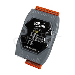
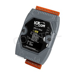
PET-7026 (AIO/DIO module), PET-7044 (DIO module), PoE switch and power supply (48V).
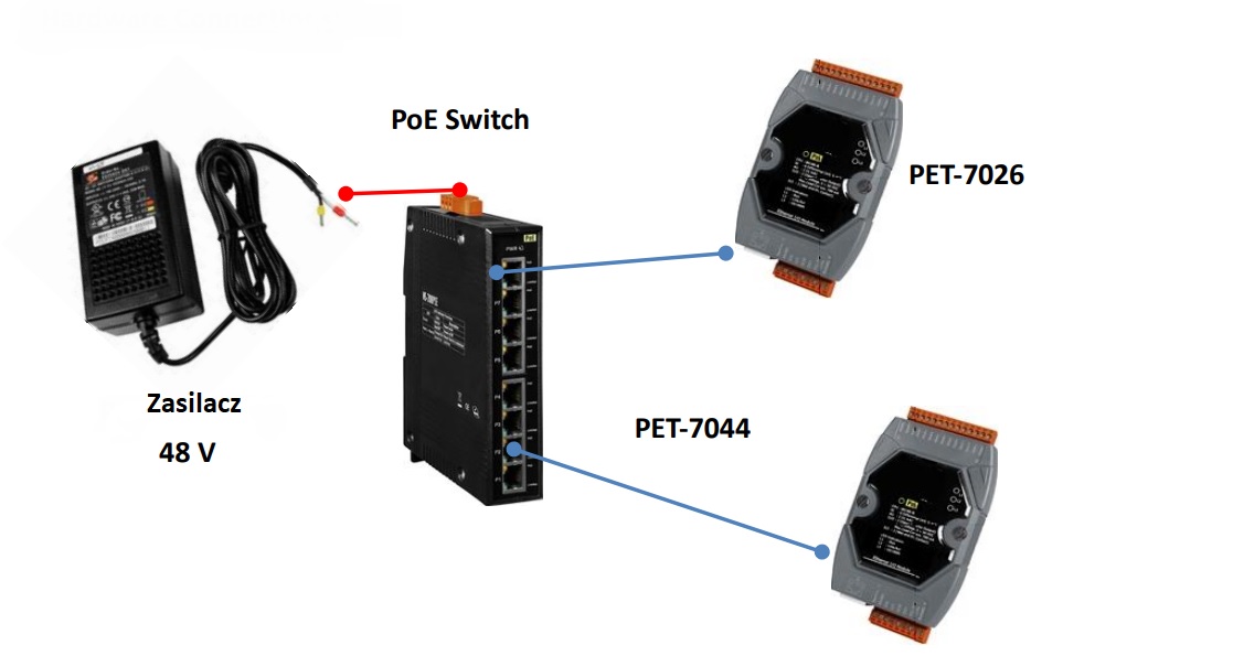
Software configuration:
The following are step-by-step instructions for configuring the ET-7X00/PET-7X00 via the built-in web interface.
In this example, the DO0/DO1 of the PET-7026 must be mapped to the DI0/DI1 of thePET-7044. Later, when the state of the DI0/DI1 is switched to ON, the state of the DO0/DO1 will be automatically switched to a high logic state.
Step 1: Log in to the PET-7026 web interface. Enter the IP address of the PET-7026 in your browser, then enter your username and password to log in to the PET-7026 web interface.
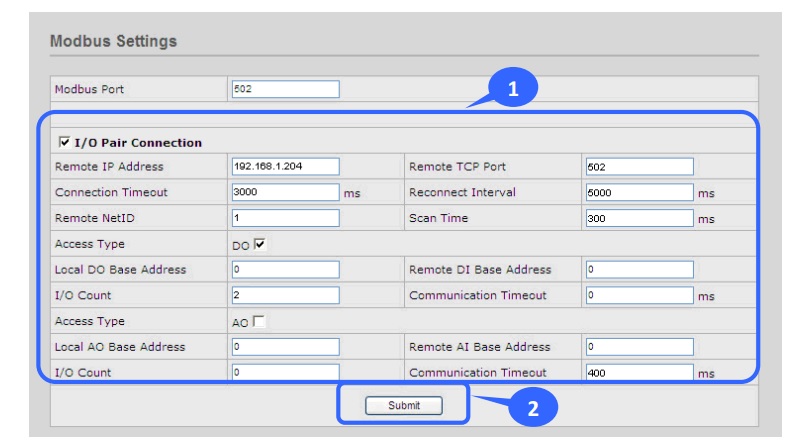
Step 2: Configure the Modbus settings for the PET-7026. Click the "Pair Connection" option on the main menu and enter the details listed in the table below into the appropriate fields.
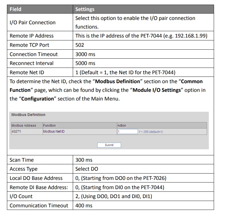
When the configuration is complete, click the "Submit" button to save the settings.
Testing:
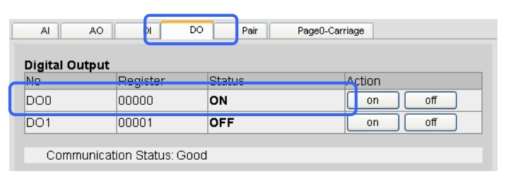
First set the DI0 status on the PET-7044 to ON, then click the "Web HMI" option in the "Web HMI" section of the main menu for the PET-7026 and click the "DO" tab. Notice that the DO0 status has changed to "ON".
Are you interested in implementing such a solution? Call us and our technical advisor will answer all your questions.

